I’ve been preparing new course materials for upcoming AUGI CAD Camps and for this year’s Autodesk University. One of the classes I’m going to be teaching at many of the future CAD Camps is a presentation on creating roofs in Revit Architecture 2008. My goal was to create a class that covers as many types of roofs as I could imagine.
As I began documenting the methods that could be used to create various roof types (I used several sources including
Architectural Graphics Standards to come up with a fairly complete list of roof types), I realized that gambrel roofs presented a special case.
A gambrel roof is usually a symmetrical two-sided roof with two slopes on each side, a lower portion with a steep slope angle and an upper portion with a shallower roof angle. The roof has gable ends. Gambrel roofs are often associated with Colonial architecture and are a common roof used on barns.

Although you could construct this roof in Revit as two roofs, the first ending at a cutoff level and the second filling the opening in the first, creating it as an extrusion works better because the roof maintains a consistent fascia along the gable end.
With the Roof by Extrusion method in Revit, you first sketch the profile of the top of the roof in an elevation or section view, and then extrude the roof. You can use a combination of straight lines and arcs to create the profile. The height of the roof depends on the location where you sketch the profile in the elevation or section view. The sketch must be a series of connected lines or arcs that are not closed in a loop.
When you start the Roof by Extrusion command, Revit displays a Work Plane dialog so you can specify the work plane on which you will sketch the roof profile. It is often helpful to sketch reference planes to guide in the placement of the profile. You can also select the Pick Plane option and then click to select an existing elevation or section; you can then sketch the profile on that plane. Revit will also ask you to specify the reference level and offset for the roof.
The Design bar changes to display the Sketch tab. You can use the sketch tools to create the profile of the roof. Note than when sketching a profile for a roof by extrusion, the Sketch tab does not include the Pick Walls, Align Eaves, or Slope Arrow tools.
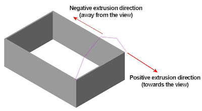
The direction in which the roof profile extrudes is known as the extrusion direction. The extrusion of the roof can extend in either direction along a plane perpendicular to the plane in which the profile is created. You use the Extrusion Start and Extrusion End controls in the Element Properties dialog to control the length of the extrusion. You can extend the extrusion towards or away from the view. Extrusion directions that are up or towards the view are positive, and extrusion directions that are down or away from the view are negative.
After first creating the exterior walls of my building and viewing my model in a plan view, here’s how I created a gambrel roof in Revit:
- On the Basics or Modeling tab of the Design Bar, select Roof > Roof by Extrusion.
Revit displays the Work Plane dialog.
- In the Work Plane dialog, select Pick a Plane (the default option), and click OK.
- Click to select one of the end elevations.
(Note that if you selected the end elevation while viewing the building in a plan view, Revit displays the Go To View dialog, and you need to complete step 4. If you were viewing the model in a 3D view, Revit skips this step and goes directly to step 5.)

- In the Go To View dialog, select one of the elevations and then click Open View. This will be the plane on which you sketch the roof profile.
Revit displays the Roof Reference Level and Offset dialog

- In the Roof Reference Level and Offset dialog, select the reference level for the roof. The default level is the highest level in the project. If desired, you can set a value to offset (raise or lower) the roof from the reference level. Click OK to continue.
The Sketch tab now displays in the Design bar.

- Use the tools on the Design bar to sketch the profile of the roof. In the case of the gambrel roof, I used the Lines tool to sketch the profile shown below.
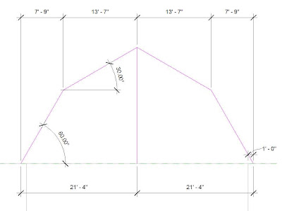
Your dimensions will likely be different from mine. But you can see how the lower slope is steeper than the upper slope. I made my roof symmetrical (which is typical for most gambrel roofs), but since this is a roof by extrusion, symmetry is not necessary.
- On the Sketch tab of the Design bar, click Properties.
Revit displays the Element Properties dialog.
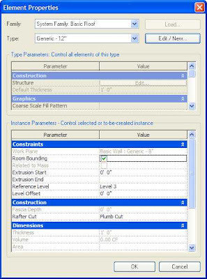
This dialog contains all of the settings for the roof you are about to create. I won’t go into a lengthy discussion of these settings. You should review these on your own (perhaps I’ll write another posting on these settings if there is interest). Normally, you would also select the roof type and adjust other settings.
The settings you need to pay attention to for a Roof by Extrusion, however, are the Extrusion Start and Extrusion End settings. In my case, I had drawn a building 60-feet long. I wanted the roof to extend 1-foot beyond the gable ends.
- In the Element Properties dialog, under Constraints, specify 1’-0” for the Extrusion Start dimension. Specify -61’-0” for the Extrusion End dimension (the length of the building plus the roof overhang.
- On the Sketch tab of the Design bar, click Finish Sketch.
At this point, you probably want to look at your model in 3D.
- On the Standard toolbar, click 3D.
Revit displays your model in 3D.
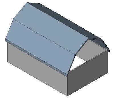
If you've drawn your building like I did, you'll notice that the end walls do not extend up to the roof. Actually, the side walls (along the long edges) don't attach to the roof yet either. That's what Revit's Attach command is for.
- Select the end wall. It immediately highlights in red.
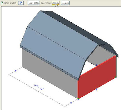
- On the Options bar, click Attach.
- On the Options bar, make sure that the Top radio button is selected, then click on the roof. Revit immediately changes the profile of the end wall so that it fills the empty space right up to the underside of the roof.
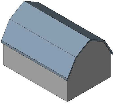
- Repeat this step for the other three walls.
That's all there is to it. Perfect gambrel roofs every time.


