Wednesday, November 14, 2007

Making Roof Lines Visible in Floor Plans

How do you make a roof overhang appear as a hidden line in a floor plan for a level below the roof?

This question keeps coming up, so I figured the best thing to do was to cover it here. While this is by no means the only solution, it is perhaps the easiest way to accomplish this.

In the plan view of the level in which you want to see the roof line, display the Element Properties dialog box for the view. Then, in the Graphics area, in the Underlay drop-down, select the level on which the roof was created to display the roof as an underlay. (Yes, I realize that the roof is probably above the level you're working on, but it's still considered an underlay nonetheless.)


This makes the roof line visible in the plan view of the level you are working on (along with any ridges and valleys), but of course the lines appear as solid lines.

To change the edges to some sort of hidden line select the Linework tool on the Tools toolbar. Then, select the desired linetype from the Type Selector drop-down. I generally choose .


Click on each roof edge line to change the linetype. To hide ridge and valley lines, you can choose from the Type Selector and then click on those lines, or simply go back to the Element Properties dialog box for the view and change the underlay back to "None."

That's all there is to it.

See. It's quite easy once you know how.

Sunday, October 21, 2007

Revit Quick Tips

The little things can certainly trip you up in Revit. Here are a couple of quick tips.

When importing a CAD file (such as an AutoCAD drawing) for use as the basis of a site plan or topo, be sure the Current View Only check box is NOT selected. Otherwise, you won't be able to select the drawing for use in creating a topo surface.


However, the opposite is true when importing or linking a CAD drawing for use within a drafting view. In order for the CAD file to be visible in the drafting view, it SHOULD be imported or linked to the Current View Only.

Also, remember that after placing the CAD drawing in the view, you can move it to the foreground or background by selecting it and then choosing the desired option on the Options bar.


Paying attention to these small details can help you avoid some frustration.

Saturday, September 29, 2007

Download the Handouts

I'm now two weeks into the fall AUGI CAD Camp season and have had the pleasure of presenting Revit classes in St. Louis, West Palm Beach, Indianapolis, and Tulsa. The reception I've received in all four cities has been wonderful, and even more impressive has been the number of attendees. Last year, many of the Revit classes had less than a dozen attendees. This year, most of the classes have had more than 40 people. In Tulsa this week, we ran out of seats in the meeting room in which the Revit classes were held.

We also ran out of some of the handouts. For that reason (and also so that attendees can get extra copies of my handouts to share with coworkers back at the office), I have posted copies of all of my handouts on my website (www.dscohn.com). While I certainly invite you to visit my website to see all of the other goodies posted there, I'm including the links below so that you download the PDF versions of the Revit handouts directly:
I'm developing additional classes for upcoming CAD Camps and will post those Revit-specific titles on-line as well once they are completed.

Saturday, September 1, 2007

AutoCAD 2008 Service Pack is Now Available

Back in early July, while I was preparing my handouts for the Honolulu AUGI CAD Camp event, I discovered several bugs in AutoCAD 2008 that affected the creation of tables. If the drawing from which you were extracting data contained dynamic blocks, the tables created from that data would not display the proper data within AutoCAD, although the data extracted to an external file, such as an Excel spreadsheet, was correct.

I reported at that time that Autodesk was aware of this problem and would be addressing it in a future service pack. That service pack has now been released, and I am happy to report that SP1 does indeed correct this problem. Tables created from drawings that include dynamic block data are now generated properly.

The service pack is available from Autodesk's website. I encourage all users of AutoCAD 2008 to download the service pack as soon as possible.

Friday, August 24, 2007

Copying Multileader Styles in AutoCAD 2008

I love the new Multileader capability in AutoCAD 2008, but while helping a client today, I discovered a somewhat glaring oversight on the part of Autodesk. Judging from postings on the AUGI forum, many other users have already discovered this problem.

The customer asked how he could copy a multileader style from one drawing to another. I naturally assumed that he could use Design Center to accomplish this. Imagine my surprise therefore when I realized that this capability was not added to Design Center in AutoCAD 2008.

After a bit of searching, I found several threads on the AUGI forum that dealt with this. There are two documented work arounds.

METHOD 1: Drawing Insertion method
  1. Open the drawing into which you want to copy the multileader style.
  2. Use the INSERT command to insert the drawing containing the desired multileader style.
  3. When AutoCAD prompts you to select the insertion point, press ESC to cancel the command.

Note that this method will also add all of the text styles, dimension styles, etc. from the drawing being inserted, which may not be desirable. If that is the case, here's another way to copy a multileader style.

METHOD 2: Tool Palette method

  1. Create a multileader in the drawing in which the desired style exists (using the style you want to copy) and then drag-and-drop that multileader onto a tool palette.
  2. Open the new drawing and then start the MLEADER command using the multileader you placed on the tool palette.

Note that this method will initially insert the exact same multileader as you created in the first drawing, including the text. But you can delete that multileader and then just use the MLEADER command normally to create new multileaders. But this method will definitely add the multileader style to the second drawing (and only the multileader style, not all of the other stuff that comes in if you use Method 1).

I would hope that the ability to copy multileader styles from one drawing to another using Design Center is high on the AUGI AutoCAD wish list. It seems silly that Autodesk neglected to add that in AutoCAD 2008. Hopefully, the company will remedy that situation very soon.

Thursday, August 23, 2007

Gambrel Roofs in Revit

I’ve been preparing new course materials for upcoming AUGI CAD Camps and for this year’s Autodesk University. One of the classes I’m going to be teaching at many of the future CAD Camps is a presentation on creating roofs in Revit Architecture 2008. My goal was to create a class that covers as many types of roofs as I could imagine.

As I began documenting the methods that could be used to create various roof types (I used several sources including Architectural Graphics Standards to come up with a fairly complete list of roof types), I realized that gambrel roofs presented a special case.

A gambrel roof is usually a symmetrical two-sided roof with two slopes on each side, a lower portion with a steep slope angle and an upper portion with a shallower roof angle. The roof has gable ends. Gambrel roofs are often associated with Colonial architecture and are a common roof used on barns.

Although you could construct this roof in Revit as two roofs, the first ending at a cutoff level and the second filling the opening in the first, creating it as an extrusion works better because the roof maintains a consistent fascia along the gable end.

With the Roof by Extrusion method in Revit, you first sketch the profile of the top of the roof in an elevation or section view, and then extrude the roof. You can use a combination of straight lines and arcs to create the profile. The height of the roof depends on the location where you sketch the profile in the elevation or section view. The sketch must be a series of connected lines or arcs that are not closed in a loop.

When you start the Roof by Extrusion command, Revit displays a Work Plane dialog so you can specify the work plane on which you will sketch the roof profile. It is often helpful to sketch reference planes to guide in the placement of the profile. You can also select the Pick Plane option and then click to select an existing elevation or section; you can then sketch the profile on that plane. Revit will also ask you to specify the reference level and offset for the roof.

The Design bar changes to display the Sketch tab. You can use the sketch tools to create the profile of the roof. Note than when sketching a profile for a roof by extrusion, the Sketch tab does not include the Pick Walls, Align Eaves, or Slope Arrow tools.

The direction in which the roof profile extrudes is known as the extrusion direction. The extrusion of the roof can extend in either direction along a plane perpendicular to the plane in which the profile is created. You use the Extrusion Start and Extrusion End controls in the Element Properties dialog to control the length of the extrusion. You can extend the extrusion towards or away from the view. Extrusion directions that are up or towards the view are positive, and extrusion directions that are down or away from the view are negative.

After first creating the exterior walls of my building and viewing my model in a plan view, here’s how I created a gambrel roof in Revit:

  1. On the Basics or Modeling tab of the Design Bar, select Roof > Roof by Extrusion.

    Revit displays the Work Plane dialog.

  2. In the Work Plane dialog, select Pick a Plane (the default option), and click OK.

  3. Click to select one of the end elevations.

    (Note that if you selected the end elevation while viewing the building in a plan view, Revit displays the Go To View dialog, and you need to complete step 4. If you were viewing the model in a 3D view, Revit skips this step and goes directly to step 5.)

  4. In the Go To View dialog, select one of the elevations and then click Open View. This will be the plane on which you sketch the roof profile.

    Revit displays the Roof Reference Level and Offset dialog

  5. In the Roof Reference Level and Offset dialog, select the reference level for the roof. The default level is the highest level in the project. If desired, you can set a value to offset (raise or lower) the roof from the reference level. Click OK to continue.

    The Sketch tab now displays in the Design bar.

  6. Use the tools on the Design bar to sketch the profile of the roof. In the case of the gambrel roof, I used the Lines tool to sketch the profile shown below.

    Your dimensions will likely be different from mine. But you can see how the lower slope is steeper than the upper slope. I made my roof symmetrical (which is typical for most gambrel roofs), but since this is a roof by extrusion, symmetry is not necessary.

  7. On the Sketch tab of the Design bar, click Properties.

    Revit displays the Element Properties dialog.

    This dialog contains all of the settings for the roof you are about to create. I won’t go into a lengthy discussion of these settings. You should review these on your own (perhaps I’ll write another posting on these settings if there is interest). Normally, you would also select the roof type and adjust other settings.

    The settings you need to pay attention to for a Roof by Extrusion, however, are the Extrusion Start and Extrusion End settings. In my case, I had drawn a building 60-feet long. I wanted the roof to extend 1-foot beyond the gable ends.

  8. In the Element Properties dialog, under Constraints, specify 1’-0” for the Extrusion Start dimension. Specify -61’-0” for the Extrusion End dimension (the length of the building plus the roof overhang.

  9. On the Sketch tab of the Design bar, click Finish Sketch.

    At this point, you probably want to look at your model in 3D.

  10. On the Standard toolbar, click 3D.

    Revit displays your model in 3D.

    If you've drawn your building like I did, you'll notice that the end walls do not extend up to the roof. Actually, the side walls (along the long edges) don't attach to the roof yet either. That's what Revit's Attach command is for.

  11. Select the end wall. It immediately highlights in red.

  12. On the Options bar, click Attach.

  13. On the Options bar, make sure that the Top radio button is selected, then click on the roof. Revit immediately changes the profile of the end wall so that it fills the empty space right up to the underside of the roof.

  14. Repeat this step for the other three walls.

That's all there is to it. Perfect gambrel roofs every time.

Monday, July 9, 2007

Warped Slabs in Revit 2008

There are lots of incredible new features in Revit 2008. One of my favorites is the ability to model slabs with multiple slopes, or what Autodesk refers to as “warped slabs.” This is a feature that was specifically highlighted in the roll-out of Revit Structure 2008, but is actually a core component of the entire Revit 2008 family.

You could create sloped slabs in previous versions of Revit, but they could only slope uniformly. It was therefore very difficult to create a floor that sloped to a floor drain, for example. But now, thanks to several new tools in Revit 2008, creating such a component if quite easy. These methods work for roofs, floors, or slabs.

After creating a slab, if you subsequently select that slab Revit displays four new tools on the Options bar:


Note that these tools will not display unless the slab is initially flat and horizontal with straight-edged boundaries. In addition, roofs cannot be attached to another roof and the roof cannot be a curtain roof.

The Modify Sub-Elements tool allows direct editing of element geometry using selection and modification points (vertices) and edges.

The Draw Points tool allows you to create new points on the top face of the slab.

The Draw Split Lines tool allows sketching directly on the top face of the slab.

The Pick Supports tool lets you pick linear beams and walls to create new split edges on the top face of the element, matching the slope to that of the underlying support.

After modifying a slab using any of these shape modifiers, Revit displays a Reset Shape button adjacent to the four shape editing tools on the Options bar. If you click this button, Revit resets the element geometry back to its original unmodified state.


In addition to these four new tools, slabs also have a new parameter enabling users to create material layers with variable thickness. When this parameter is active, the non-variable layers will maintain their specified thickness while the variable layer will adjust its thickness based on the slope. This is a great way to create roof with tapered insulation board, for example.

To modify a slab using the Modify Sub-Elements tool:

  1. Select the slab, roof, or floor you want to modify.
  2. On the Options bar, click the Modify Sub-Elements tool.
  3. Click to select a vertex or edge, after which you can do one of the following:
    • Drag the blue arrows to move the point vertically.
    • Drag the red square to move the point horizontally.
    • Click the text control to enter a precise height for the selected point or edge.
    • Enter a precise height in the Elevation edit box on the Options bar.
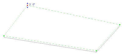
Note that the value of the height represents the offset from the original top face of the slab. For an edge, the entire edge is moved to the specified height.

To modify a slab using the Draw Points tool:

  1. Select the slab, roof, or floot you want to modify.
  2. On the Options bar, click the Draw Points tool.
  3. Click on the face or edges of the slab, roof, or floor to add points that define a slope.

Note that when you select the Draw Points tool in step 2, the Options bar displays an Elevation text box. The value in this box determines the elevation of the point you are about to add. When the adjacent Relative check box is selected, the elevation is mearsured relative to the surface on which you are adding the point. When this check box is cleared, the elevation represents the actual project elevation and points will be added at this specific elevation.

In this illustration, I simply warped the slab down to a central point by adding a new point in the center of the room. The elevation of this point is below the elevation at which the slab was originally created.

When you add new points, Revit automatically splits the slab into smaller sub-regions. You can use the Draw Split Lines tool to manually split an existing face of a slab into smaller sub-regions. You can then alter the elevation of vertices and/or edges of that sub-region to warp the slab.

To modify a slab using the Draw Split Lines tool:

  1. Select the slab, roof, or floor you want to modify.
  2. On the Options bar, click the Draw Split Lines tool.
  3. Select a vertex, edge, face, or point anywhere on the slab to start the split line.
  4. Select another vertex, edge, face, or point anywhere on the slab to end the split line.

Note that the startpoints and endpoints of the split lines can be added anywhere on the face of the slab. If your cursor is over a vertex or edge, Revit will snap to 3D vertices and edges and present standard snap controls and temporary dimensions along the edge.

In the illustrations above, I first added a single split line across the entire slab on the left and then used the Modify Sub-Elements tool to raise the elevation of that split line. To create the slab on the right, I first added four new split lines (using the Chain option when drawing the split lines) and then used the Modify Sub-Elements tool to lower the elevation of the new split lines to create the trench drain.

Note that in all of the previous examples, the overall thickness of the slab remains constant and is simply warped to take on the new slope.


That isn't always what you are trying to achieve. Sometimes, such as in the case of tapered insulation on an otherwise flat roof, you want to keep the actual structure flat and simply create a layer within the roof assembly that has a variable thickness, to represent the tapered insulation. You can accomplish this by creating a variable thickness slab.

Any one layer within the structure of a slab, roof, or floor can have a variable thickness. To modify the structure of a layer to make it a variable layer:

  1. Select the slab, roof, or floor to modify.
  2. Display its Element Properties dialog box.
  3. Click the Edit/New button.
  4. In the Type Properties dialog box, click the Edit button in the Structure property.
  5. In the Edit Assembly dialog box, select the check box in the Variable column for the layer you want to have a variable thickness.
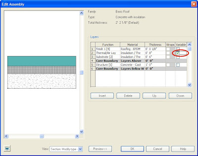

  6. Click OK until all the dialog boxes are closed.

You can then select the slab and use the Modify Sub-Elements tool to make the desired changes to the slab. Only the thickness of the variable layer will change.