Since this was a residence, his construction documents would not include reflected ceiling plans. Instead, he wanted the skylights in a clearstory ceiling to appear on the second floor plan as a hidden line.
While there may be several ways to accomplish this, it seemed like an obvious solution was to create a filter. Filters provide a way to override the graphic appearance and visibility of all elements that share common properties. For example, the controls in Revit’s Visibility/Graphics dialog box let you change the color applied to walls, but the change would apply to all walls. But if you only wanted to change the color for 2-hour fire rated walls, you could create a filter that would select just those 2-hour walls and then apply the desired visibility change to just those walls.
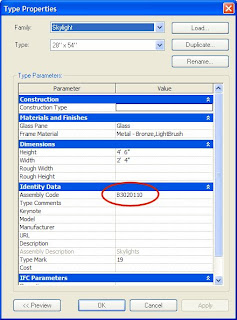
To accomplish the client’s desired result (skylights shown in the second floor plan as a hidden line), I first looked at the properties of one of the skylights and found that it was assigned an assembly code of B3020110.

Using that piece of information that is unique to the skylights, I created a filter using the following steps:
- Display the Second Floor plan view.
- Open the Visibility/Graphics Overrides dialog box.
- Select the Filters tab.
- Click the Edit/New button to display the Filters dialog box.
- Click the New button to create a new filter.
- In the Filter Name dialog box, name the new filter “Skylight” and click OK
- Back in the Filters dialog box, under Categories, select the Window category check box.
- Under Filter Rules, in the first Filter By drop-down, select Assembly Code, set it equal to B3020110 (the unique code assigned to the skylights), and then click OK. Take care when entering this assembly code. Remember that the value you enter is case-sensitive.
- Back in the Visibility/Graphics Overrides dialog box, click the Add button.
- In the Add Filters dialog box, select the Skylight filter you just created, and then click OK.
- Back in the Visibility/Graphics Overrides dialog box, under Projection/Surface, in the Lines column, click the Override button. We’re applying the override to the lines projected down from the skylight above.
- In the Line Graphics dialog box, from the Pattern drop-down list, select the Hidden line type, and then click OK.
- Click OK to close the Visibility/Graphic Overrides dialog box.
At this point, the skylight still may not appear in the plan view, because the View Range is most likely still set to its default condition, which is to only extend 10-feet above the current floor level when looking up for objects that should appear in the current view.
If you think about the way Revit creates a view, imagine the 3D building model is suspended inside of a transparent cube. The sides of the cube determine what’s visible in any given view. You’ve already probably experienced the sides of this cube—it’s what Revit calls the “Crop Region.” The top and bottom of this cube define the “View Range.”
The view range is a set of horizontal planes that control the object visibility and appearance in the view. The horizontal planes are Top, Cut Plane, Bottom, and View Depth. As their names imply, the top and bottom planes represent the top-most and bottom-most portion of the view range. The cut plane is a plane that determines at what height certain elements in the view are shown cut. These three planes define the Primary Range of the view range. View Depth is an additional plane outside the primary range. You can set the level of view depth to show elements below the bottom plane. By default, it is the same as the bottom plane.
Elements outside of this view range do not display in the view. The exception to this is if you set the view Underlay to a level outside the visible range.
Elements within the boundaries of the primary range that are not cut by the cut plane are drawn in a projection line style, which is why we assigned the hidden line to the projection line setting when we created the Skylight filter.
In order for the skylights to appear in the second floor plan view, we need to change the view range so that it extends up at least to the roof. To do this:
- Display the Element Properties dialog box for the Second Floor plan view (for example, right-click in the view and choose View Properties from the shortcut menu.
- In the Element Properties dialog box, click the View Range Edit button.
- In the View Range dialog box, change the Top plane setting so that it extends above the roof. There are several ways in which you could do this. You could simply change the Offset value so that the plane is far enough above the roof, or you could choose a different level (or “Unlimited”) from the Top drop-down list.
- Click OK to close all of the dialog boxes.
The skylights should now be visible in the second floor plan view.


1 comment:
I am looking for a way to turn off everything in the structural model except that steel when I import it into the Architectural model. Only way I've found so far is to go into each view and change them one at a time with visibilty graphics menu. Is there an easier way of doing this?
Post a Comment