There are lots of incredible new features in Revit 2008. One of my favorites is the ability to model slabs with multiple slopes, or what Autodesk refers to as “warped slabs.” This is a feature that was specifically highlighted in the roll-out of Revit Structure 2008, but is actually a core component of the entire Revit 2008 family.
You could create sloped slabs in previous versions of Revit, but they could only slope uniformly. It was therefore very difficult to create a floor that sloped to a floor drain, for example. But now, thanks to several new tools in Revit 2008, creating such a component if quite easy. These methods work for roofs, floors, or slabs.
After creating a slab, if you subsequently select that slab Revit displays four new tools on the Options bar:
Note that these tools will not display unless the slab is initially flat and horizontal with straight-edged boundaries. In addition, roofs cannot be attached to another roof and the roof cannot be a curtain roof.
The Modify Sub-Elements tool allows direct editing of element geometry using selection and modification points (vertices) and edges.
The Draw Points tool allows you to create new points on the top face of the slab.
The Draw Split Lines tool allows sketching directly on the top face of the slab.
The Pick Supports tool lets you pick linear beams and walls to create new split edges on the top face of the element, matching the slope to that of the underlying support.
After modifying a slab using any of these shape modifiers, Revit displays a Reset Shape button adjacent to the four shape editing tools on the Options bar. If you click this button, Revit resets the element geometry back to its original unmodified state.
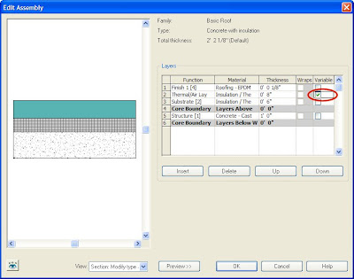
In addition to these four new tools, slabs also have a new parameter enabling users to create material layers with variable thickness. When this parameter is active, the non-variable layers will maintain their specified thickness while the variable layer will adjust its thickness based on the slope. This is a great way to create roof with tapered insulation board, for example.
To modify a slab using the Modify Sub-Elements tool:
- Select the slab, roof, or floor you want to modify.
- On the Options bar, click the Modify Sub-Elements tool.
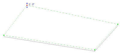
- Click to select a vertex or edge, after which you can do one of the following:
- Drag the blue arrows to move the point vertically.
- Drag the red square to move the point horizontally.
- Click the text control to enter a precise height for the selected point or edge.
- Enter a precise height in the Elevation edit box on the Options bar.

Note that the value of the height represents the offset from the original top face of the slab. For an edge, the entire edge is moved to the specified height.
To modify a slab using the Draw Points tool:
- Select the slab, roof, or floot you want to modify.
- On the Options bar, click the Draw Points tool.
- Click on the face or edges of the slab, roof, or floor to add points that define a slope.
Note that when you select the Draw Points tool in step 2, the Options bar displays an Elevation text box. The value in this box determines the elevation of the point you are about to add. When the adjacent Relative check box is selected, the elevation is mearsured relative to the surface on which you are adding the point. When this check box is cleared, the elevation represents the actual project elevation and points will be added at this specific elevation.
In this illustration, I simply warped the slab down to a central point by adding a new point in the center of the room. The elevation of this point is below the elevation at which the slab was originally created.
When you add new points, Revit automatically splits the slab into smaller sub-regions. You can use the Draw Split Lines tool to manually split an existing face of a slab into smaller sub-regions. You can then alter the elevation of vertices and/or edges of that sub-region to warp the slab.
To modify a slab using the Draw Split Lines tool:
- Select the slab, roof, or floor you want to modify.
- On the Options bar, click the Draw Split Lines tool.
- Select a vertex, edge, face, or point anywhere on the slab to start the split line.
- Select another vertex, edge, face, or point anywhere on the slab to end the split line.
Note that the startpoints and endpoints of the split lines can be added anywhere on the face of the slab. If your cursor is over a vertex or edge, Revit will snap to 3D vertices and edges and present standard snap controls and temporary dimensions along the edge.
In the illustrations above, I first added a single split line across the entire slab on the left and then used the Modify Sub-Elements tool to raise the elevation of that split line. To create the slab on the right, I first added four new split lines (using the Chain option when drawing the split lines) and then used the Modify Sub-Elements tool to lower the elevation of the new split lines to create the trench drain.
Note that in all of the previous examples, the overall thickness of the slab remains constant and is simply warped to take on the new slope.

That isn't always what you are trying to achieve. Sometimes, such as in the case of tapered insulation on an otherwise flat roof, you want to keep the actual structure flat and simply create a layer within the roof assembly that has a variable thickness, to represent the tapered insulation. You can accomplish this by creating a variable thickness slab.
Any one layer within the structure of a slab, roof, or floor can have a variable thickness. To modify the structure of a layer to make it a variable layer:
- Select the slab, roof, or floor to modify.
- Display its Element Properties dialog box.
- Click the Edit/New button.
- In the Type Properties dialog box, click the Edit button in the Structure property.
- In the Edit Assembly dialog box, select the check box in the Variable column for the layer you want to have a variable thickness.
- Click OK until all the dialog boxes are closed.

You can then select the slab and use the Modify Sub-Elements tool to make the desired changes to the slab. Only the thickness of the variable layer will change.


No comments:
Post a Comment